
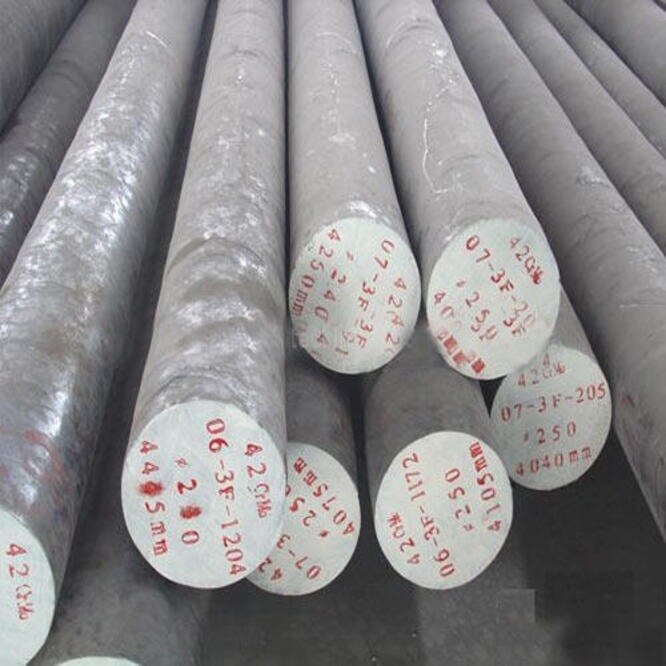
A damaged Inconel component can fail through cracking, localized corrosion, erosion, thermal cycling or an incorrect heat-treatment condition, and the visible failure point is not always the origin. By following a controlled evidence-preservation, inspection and grade-identification sequence, you can separate the damage mechanism from the material-selection problem and choose a defensible repair or replacement route.
Key takeaways
- Apply lockout/tagout and verify zero stored energy before inspection.
- Photograph orientation, damage patterns and initiation sites before cleaning the part.
- Confirm the alloy grade and reconstruct temperature, chemistry, pressure and cycle history.
- Use targeted NDT results to choose repair, grade change or replacement.
Secure the Equipment and Preserve Evidence Before Inspection
First isolate the equipment before touching the removed Inconel component. Apply lockout/tagout, depressurize, drain and cool the system, then verify zero stored energy. Record the component’s orientation, location, operating side and removal date before moving it.
1. Photograph the part in place and immediately after removal. Include wide views, close-ups, a scale, welds, gaskets, deposits, distortion and every visible crack or pit.
2. Protect fracture surfaces from cleaning, wire-brushing, grinding, welding and sectioning. These actions can erase beach marks, corrosion products, rubbing patterns and the original crack origin. Use high-resolution photographs or a surface replica before any destructive preparation.
3. Tag the component with its equipment number, flow direction, alloy designation, heat or lot number and removed condition. Keep loose deposits, corrosion products and gasket fragments in labelled, sealed containers rather than discarding them.
4. Preserve the service record with temperature and pressure ranges, startup and shutdown cycles, fluid pH, chloride, fluoride, dissolved oxygen, cleaning chemicals, chemistry excursions, flow changes and exposure duration. Note leak paths, stagnant zones, deposits and wet/dry cycling.
For inconel damage troubleshooting in indore, do not blame inland weather for chloride or caustic attack. Tie the damage to process fluid, cooling-water chemistry, cleaning history or a specific deposit. “Inconel” is a family name, so confirm the exact grade, product form, heat treatment and heat/lot number before cleaning, sectioning or recommending a replacement alloy.
Map the Damage and Match Its Appearance to a Failure Mechanism
Physical appearance gives a useful first split: corrosion removes or attacks metal, cracking creates a narrow discontinuity, wear changes a contact or flow surface, and thermal failure leaves oxidation, distortion or heat-cycle cracks.
- Corrosion appears as uniform thinning, isolated pits, under-deposit attack or a sharp-edged cavity at a gasket, crevice or deposit. A clean exposed surface does not clear the part: Inconel 625 can corrode beneath deposits, while Inconel 600 can crack in hot caustic or chloride-bearing service without obvious wall loss.
- Cracking appears as fine, branching or linear openings, often starting at weld toes, pits, threads, bends or restraint points. Tight cracks aligned with the stress direction suggest stress-corrosion cracking; multiple cracks across a cyclically loaded surface suggest corrosion-fatigue. Lift a deposit before calling the surface sound.
- Wear produces directional grooves, polished bands, smeared metal, galling or repeated contact marks. Erosion follows flow paths and elbows; cavitation leaves clustered, rough “sponge-like” pits near pressure changes rather than random corrosion pits.
- Thermal failure leaves blue, black or green oxide, heat tint, scaling, distortion, bulging or softened areas. Repeated temperature changes can create branched cracks at restraints and welds. On Inconel 600, exposure around 500–850 °C can sensitize grain boundaries, making intergranular corrosion or cracking appear as a network along the boundaries.
Photograph each feature with a scale, record its distance from welds and flow changes, and map depth and direction before cleaning aggressively. Do not label the cause from appearance alone; confirm it against deposits, hardness, fracture surfaces and service chemistry.
Reconstruct the Service Conditions and Check the Alloy Grade
Do not diagnose from damage appearance alone: establish what the component was made from and what it experienced. Retrieve the purchase order, material certificate, heat or lot number, product form, delivery condition, weld procedure, repair records and heat-treatment charts.
Inconel 600 is nickel-chromium-iron; Inconel 625 is nickel-chromium-molybdenum-niobium; Inconel 725 also contains titanium and aluminium and gains strength through precipitation hardening. Portable X-ray fluorescence can show molybdenum, but it cannot replace full PMI when carbon, niobium, titanium, aluminium or heat treatment matters.
Collect these service records before selecting a failure mechanism:
- Actual metal and fluid temperatures, including peaks, gradients, startup and shutdown cycles, pressure excursions and exposure duration.
- Process chemistry: pH, chloride, fluoride, dissolved oxygen, sulfur, caustic concentration, cleaning agents, deposits and cooling-water results.
- Flow velocity, vibration, cavitation reports, solid-particle loading, leak paths and wet-dry cycling.
- Weld locations, repair dates, post-weld heat treatment, final machining and any unexpected process interruption.
- Hardness readings from unaffected material through the damaged zone; use them as screening evidence, not proof of the correct heat-treatment condition.
| Grade | Chemistry or condition to confirm | Check that prevents a wrong diagnosis |
|---|---|---|
| Inconel 600 | Nickel-chromium-iron | PMI and certificate match; verify no mistaken substitution for a molybdenum-bearing grade. |
| Inconel 625 | Molybdenum and niobium present | Confirm by PMI, then optical-emission or laboratory analysis if the chemistry is disputed. |
| Inconel 725 | Precipitation-hardened condition | Verify solution treatment, aging temperature and time, aging after final machining, and any weld repair; check for overaging. |
Use the Right Inspection Method at the Likely Initiation Sites
A clean surface does not prove a sound component. Inspect beneath deposits, gaskets, clamps and crevice shields, then examine every weld metal zone, fusion boundary and heat-affected zone separately.
| Method | Reveals | Best application |
|---|---|---|
| Liquid-penetrant testing | Open-to-surface cracks | Clean, nonporous surfaces; useful for weld toes and thermal-fatigue cracks |
| Ultrasonic thickness mapping | Local wall loss and pitting depth | Scan beneath scale, deposits and insulation; record a grid, not one thickness reading |
| Phased-array ultrasonic testing | Planar and volumetric subsurface flaws | Thick sections, welds and suspected crack planes |
| Radiographic testing | Volumetric porosity, inclusions and lack of fusion | Weld inspection where access and flaw orientation suit radiography |
| Metallography and hardness testing | Grain changes, precipitates, overaging and soft zones | Cut a representative sample or use a surface replica before destructive sampling |
Use liquid penetrant on Inconel 625 or Inconel 725 only after degreasing and removing oxide without smearing a crack closed. Ultrasonic or radiographic testing must follow when the suspected defect lies below the surface; no single NDT method excludes every failure mode.
- For extended high-temperature exposure of Inconel 625, request metallography and fracture-toughness evidence; delta phase and other precipitates can reduce ductility while room-temperature hardness appears acceptable.
- For Inconel 725, verify solution treatment and aging condition through records and hardness mapping; an unsuitable thermal cycle can overage the alloy or leave a major strength shortfall.
Decide Whether to Repair, Change the Grade or Replace the Part
Do not specify a new alloy from appearance alone. Convert the evidence into a decision only after matching the crack, corrosion or wear mechanism to the verified grade, product form, heat treatment and heat or lot number.
Inconel damage troubleshooting in Indore must link chloride or caustic attack to process chemistry, deposits, cleaning agents and wet/dry cycling—not to the city’s inland climate.
| Option | What it means | When it applies |
|---|---|---|
| Repair | Restore the existing part under an approved welding, heat-treatment and inspection procedure | The mechanism is controlled, remaining dimensions meet design limits, and qualified NDE finds no unacceptable cracks |
| Change grade | Select a different alloy and redesign the specification | Verified chemistry, temperature, strength or cracking conditions exceed the present grade’s suitability |
| Replace part | Make a new component to the confirmed design and material specification | A pressure boundary is cracked through, wall loss exceeds the minimum, distortion cannot be removed, or repair would leave uncertain integrity |
For Inconel 725, record whether aging occurred after final machining, the actual aging temperature and time, and every weld repair. Map hardness from unaffected metal into the damaged zone, but do not treat hardness alone as proof of the precipitation condition.
Do not replace Inconel 600 with Inconel 625 simply because cracking occurred; 600 can suffer caustic or chloride stress-corrosion cracking when tensile stress exists. Choose 625 or 725 only after correcting stress and chemistry where necessary.
Ask Steel Mart for the heat number, mill certificate, full chemistry, product form and heat-treatment condition, then verify them by PMI and laboratory analysis when alloying elements or aging condition matter.
Frequently asked questions
How should you secure equipment before inspecting damaged Inconel?
Apply lockout/tagout, depressurize, drain and cool the system, verify zero stored energy, then record the component’s orientation, location, operating side and removal date.
How do you distinguish Inconel damage mechanisms from appearance?
Map cracks, pits, thinning, deformation and deposits, then compare their location and pattern with likely mechanisms such as fatigue, corrosion, erosion, oxidation or overheating.
Which service details matter when troubleshooting Inconel damage?
Check the alloy designation, including Inconel 600, Inconel 625 or Inconel 725, and reconstruct operating temperature, pressure, fluid chemistry, loads, cycles and upset events.
How do you choose an inspection method for a damaged Inconel part?
Select inspection around likely initiation sites: visual examination for surface patterns, dye penetrant or magnetic particle testing for surface-breaking flaws where suitable, ultrasonic testing for internal defects and dimensional checks for distortion or wear.
When should you repair, change the alloy grade or replace an Inconel component?
Repair when the damage is fully characterised and repair leaves adequate design margin; change grade when service conditions exceed the current alloy’s resistance; replace the part when cracks, section loss or distortion compromise safe geometry or inspection cannot establish its integrity.