
A pressure-equipment defect is not automatically a plate problem, and welding over the visible damage can conceal a crack, lamination, hydrogen blister, or design shortfall. By the end, you will have a practical sequence for identifying the damage mechanism, verifying replacement material, selecting the repair scope, and deciding whether the equipment is ready to return to service.
Key takeaways
- Map the indication before cutting, using a calibrated ultrasonic thickness grid.
- Relate damage to welds, flow paths, supports, and heat-affected areas.
- Verify plate grade, certification, dimensions, and calculated minimum thickness.
- Keep material compliance separate from welding inspection and repair acceptance.
Identify the Failure Mechanism Before You Plan a Plate Repair
A repair decision starts with mapping the indication, not cutting it out. Use a calibrated ultrasonic thickness grid, then relate each reading to the shell course, welds, flow path, supports, and heat-affected areas. Record shape, depth, orientation, and the response from surface and volumetric examination.
1. Treat isolated deep cavities as pitting; broad, shallow wall loss as general thinning; and narrow channels beside welds, baffles, or flow paths as grooving or erosion. Average wall thickness cannot dismiss a deep pit.
2. Treat a planar internal reflector that follows the plate’s rolling direction as a possible lamination. A weld-aligned reflector or linear surface indication points toward lack of fusion, incomplete penetration, or a weld crack rather than damaged plate.
3. Treat bulged, layered, or separated regions as hydrogen blistering, especially on the wet side of equipment exposed to hydrogen-producing service. Sharp linear indications require crack assessment for fatigue or brittle fracture; their length, tips, orientation, and growth history matter more than surrounding average thickness.
4. Check distortion and thermal damage by comparing shell geometry, weld alignment, hardness, colour, microstructure, and local thickness with undamaged areas. Warping near a weld or hot spot suggests restraint, overheating, or an operating excursion; repeated cycling, vibration, pressure swings, and poor support suggest fatigue.
5. Test the operating and design explanation against service fluid, temperature, pressure, flow velocity, dead zones, and previous repairs.
“Boiler plate” does not prove suitability for the vessel design or repair code, so investigate sa 516 gr 70 boiler plate problems and sa 516 gr 70 plate for problems through the drawing, data report, material certificate, and governing code.
Use a Controlled Field Inspection Sequence and Build the Evidence File
1. Read the nameplate before touching the pressure boundary. Record the construction code, design pressure, design and minimum metal temperatures, service fluid, corrosion allowance, shell or head thickness, and repair history. Compare these details with original drawings and the manufacturer’s data report; “boiler plate” alone proves nothing about suitability.
2. Isolate, drain, clean, depressurise, and vent the equipment. Gas-test the work area and vessel before entry, hot work, grinding, or welding. Cutting into trapped pressure or residue can turn a local repair into a fatal release.
3. Establish a calibrated ultrasonic thickness grid across the damaged area and sound surrounding metal. Record grid spacing, readings, instrument identification, calibration block, operator, and minimum values. Photograph each indication, mark its location and orientation on the equipment, and compare the map with previous inspection maps and thickness trends.
4. Examine welds using the combination that fits the indication and geometry: visual testing for profile and workmanship; magnetic particle testing for surface and near-surface indications in ferromagnetic steel; dye penetrant testing where surface-breaking flaws require it; ultrasonic testing for internal reflectors; and radiography where weld geometry or the governing code requires an image.
Do not cut, grind, weld, or order replacement material until the damage boundary and mechanism are defined.
5. Assemble the approval file with the MTR, heat number, plate thickness, normalized or supplied condition, impact-test status, carbon equivalent or weldability data, fabrication code, design conditions, corrosion allowance, service fluid, prior repairs, drawings, data report, inspection maps, thickness trends, photographs, and all NDE reports.
Confirm every record identifies the SA 516 Gr 70 pressure equipment plate and the affected vessel.
Verify the Replacement Plate and Calculate the Required Thickness
Do not accept “A516 Grade 70” on a quotation as proof of suitability. For a SA 516 Gr 70 pressure equipment plate, trace the heat number stamped or transferred onto the plate to the mill test certificate (MTC), then match the certificate to the vessel records and repair specification.
1. Check the MTC for the stated SA 516 or ASTM A516/A516M designation, heat number, ordered thickness, supplied or normalized heat-treatment condition, chemical analysis, tensile strength, yield strength, and elongation. The commonly cited minimums of 70 ksi tensile strength and 38 ksi yield strength confirm neither low-temperature toughness nor repair suitability.
2. Confirm Charpy impact-test temperature, absorbed-energy acceptance criteria, and test results when required by the purchase order, design temperature, construction code, or supplementary requirement. SA 516 Grade 70 does not automatically guarantee impact toughness. A plate can meet the grade and still fail the vessel’s low-temperature requirement.
3. Size the replacement for the calculated minimum required thickness, not the old plate’s nominal dimension. Include corrosion allowance, future corrosion rate, forming losses, weld efficiency, local stress, nozzle reinforcement, and thickness transitions. A thicker insert can still create an abrupt stiffness change or an unqualified weld detail.
For a SA 516 Gr 70 plate repair, Steel Mart can provide traceable material documentation; the purchaser and repair engineer must still match each heat, thickness, chemistry, toughness result, and supplied condition to the governing code and vessel file.
Related product
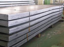 | BQ and Wear Resistant Plates SA 516 Gr 60-70 Boiler Quality Plate SA 516 Grade 60 / Grade 70 Boiler Quality Plate is a pressure vessel quality carbon steel plate designed for medium to low-temperature service. View product → |
Choose the Repair Geometry and Control Welding Risks
Choose an insert only when the damaged boundary is fully defined and UT plus NDE confirm sound surrounding plate. A SA 516 Gr 70 plate repair becomes larger when corrosion is widespread, damage reaches a seam or attachment, or too little sound weld land remains. Do not weld across laminations, hydrogen blisters, or unidentified metal.
| Option | Best fit | Main control |
|---|---|---|
| Welded insert | Local, bounded loss with sound land | Match thickness transition, weld orientation and local-stress limits |
| Larger replacement section | Widespread corrosion, seam or attachment damage | Remove all affected metal and restore reinforcement and geometry |
| Overlay | Broad shallow thinning without cracks or unstable substrate | Confirm bonding, corrosion mechanism and examination access |
| Weld build-up | Small, clean excavation with stable base metal | Use only with qualified procedure and final contour control |
| Mechanical repair | Service constraint or welding risk prevents hot work | Define pressure, temperature, leakage and inspection limits |
| Design modification or retirement | Recurrent damage, inadequate geometry or unsafe remaining metal | Recalculate the boundary, alter the design, or remove from service |
- Qualify the WPS and PQR for the actual base-metal specification and P-Number grouping, thickness range, welding process, consumables, preheat, interpass temperature, PWHT and impact requirements. A SA 516 Gr 70 plate for problems is not automatically weldable under a generic carbon-steel procedure.
- Control hydrogen with dry low-hydrogen electrodes or flux, specified storage and baking, and a qualified repair sequence. Set preheat from carbon equivalent, thickness, restraint, joint geometry and ambient conditions; control cooling rate and avoid abrupt weld termination.
- Apply PWHT only as the governing code requires. Temporary patches and unengineered clamps need explicit pressure-service limits and approval; they are not permanent code repairs by default.
Separate Material Compliance from Repair Acceptance Before Return to Service
A compliant SA 516 Grade 70 plate proves only material identity and specified properties. It does not prove that the completed repair can return pressure equipment to service.
1. Confirm the approved repair design, including drawings, calculations, weld geometry, required thickness, corrosion allowance, thickness transitions, and local stress. Check that nozzle reinforcement remains adequate and that shell, head, and support loads still transfer safely.
2. Verify the WPS, PQR, and welder records for the actual base-metal specification, P-Number grouping, thickness range, process, consumables, preheat, interpass temperature, weld sequence, PWHT, and impact requirements. A welder’s experience with carbon steel does not qualify this repair.
3. Examine the excavated area before welding and the finished weld afterward using the governing code and repair procedure. Use visual and surface NDE such as magnetic particle or liquid penetrant testing, plus volumetric UT or radiography where geometry and code require it.
A filled corrosion cavity or ground-out crack is not acceptance evidence by itself.
4. Confirm that the repair addresses the cause: corrosion, erosion, fatigue, hydrogen damage, or overheating. Resolve SA 516 Gr 70 boiler plate problems at the source, or the new insert will repeat the failure. Pressure-test the equipment when required.
5. Apply PWHT based on thickness, material grouping, weld type, service, design temperature, and code exemptions—not the grade name alone. Assemble approved drawings and calculations, material certificates, NDE reports, heat-treatment charts, pressure-test records, and an updated inspection baseline, with jurisdictional or authorized-inspector approval.
A change to a nozzle, shell course, support, pressure boundary, or design condition may be an alteration, not a simple SA 516 Gr 70 plate repair.
Frequently asked questions
How do you identify the failure mechanism before an SA 516 Gr 70 plate repair?
Map the indication with a calibrated ultrasonic thickness grid, then compare its shape, depth, orientation, and examination response with nearby welds, flow paths, supports, and heat-affected areas.
What evidence should you collect during a pressure equipment plate inspection?
Build an evidence file containing thickness-grid readings, photographs, indication dimensions, surface examination results, volumetric examination results, location references, and relevant operating history.
How do you verify replacement SA 516 Gr 70 plate and required thickness?
Check the material certificate, heat or batch identification, grade, dimensions, test results, and traceability, then calculate required thickness from design conditions, corrosion allowance, joint efficiency, and applicable code rules.
How do you control welding risks during an SA 516 Gr 70 plate repair?
Select a repair geometry that removes the damaged material without creating sharp transitions, then control the qualified welding procedure, preheat, interpass temperature, consumables, heat input, and post-weld examinations.